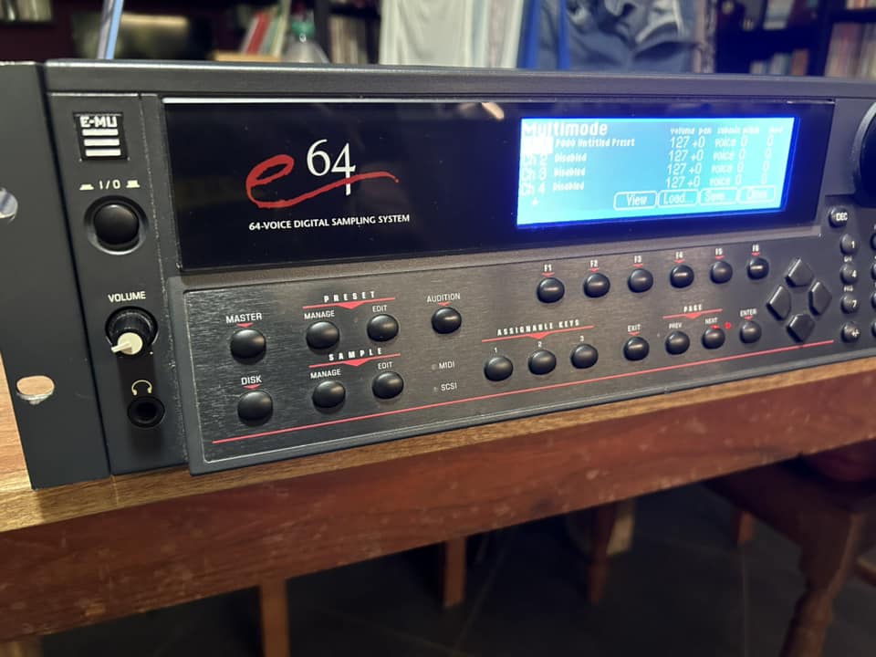
I recently bought an E-MU E64 on Ebay, quite cheap (paid 150 euros for it), but the screen was really dim, almost unreadable, so I soon decided to replace it.
After a quick search I came up with this 240x64 LCD Display on Aliexpress for about 25 Euros. It arrived after about 10 days and worked perfectly.
Here's a short guide on how to replace the screen:
1) unscrew the unit, the rack ears first and then all the metal chassis. The front panel is held in place by a couple of screws on the sides, and then to reach the display you need to unscrew a metal plate just behind the front panel. The display is then just held by 4 screws
2) disconnect all connectors and ribbon cables from the front panel, including the flat cable connecting the display to the motherboard and the connector going to the inverter (you won't need it anymore).
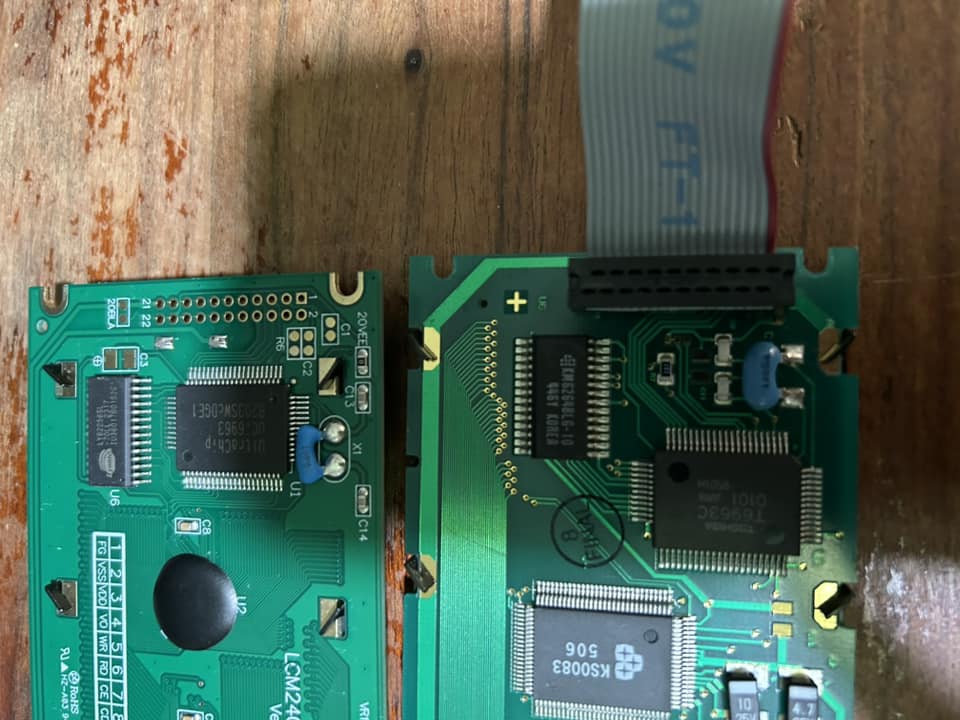
3) once the display is free, you will need to desolder the connector (this was the most boring part). See the old (below) and the new one (above) in this pic: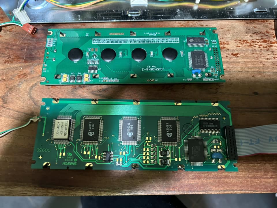
4) the size of the new display was identical, it's only a bit "taller" than the old one but you can fit it.
The main difference is the old one has 20 pins, while the new one has 22 pins. Luckily, pins 1-20 are identical. Pins 21 and 22 are for the LED backlight: 21 is for the +5V and 22 is for 0V
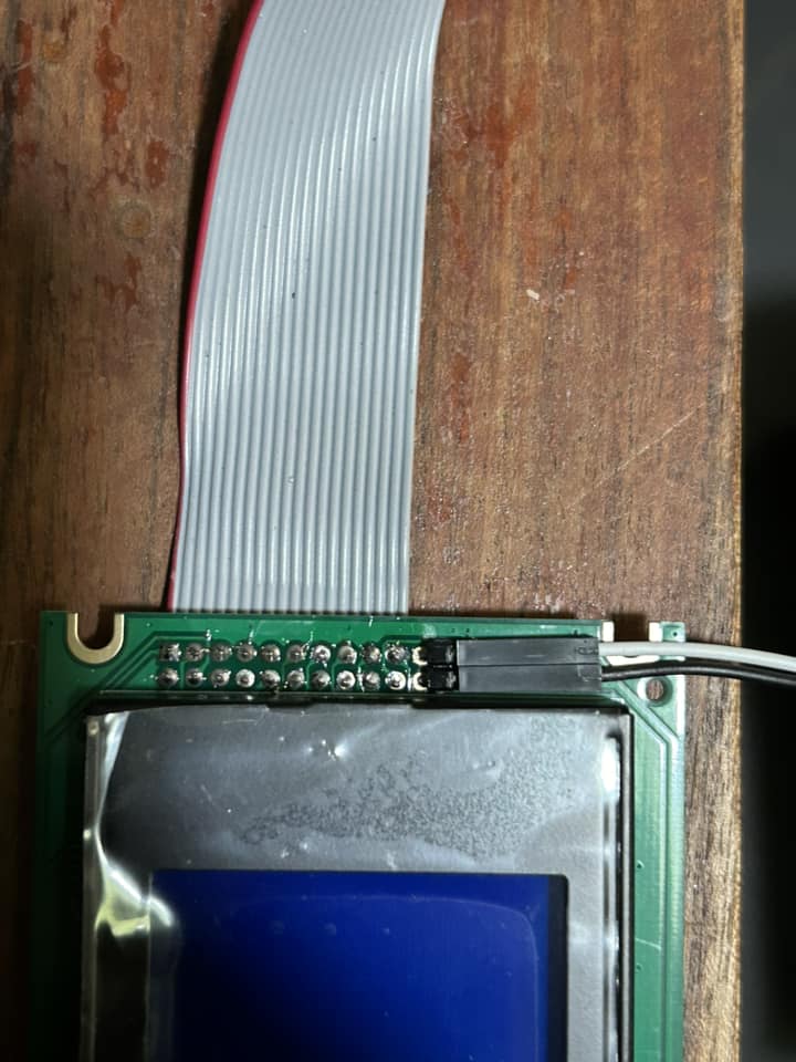
5) resolder the 20-pin connector back on the new display, and then connect a couple of wires to pin 21 and 22. I used a couple of headers that I had previously bent, but you can also solder the wires direcly on the 2 pads. These 2 pads need to be connected to +5V and 0V, and this can easily be obtained from the cables going to the Hard Drive or Floppy connectors. I simply stripped half centimeter of cable naked, and soldered these 2 cables to get the correct voltages.
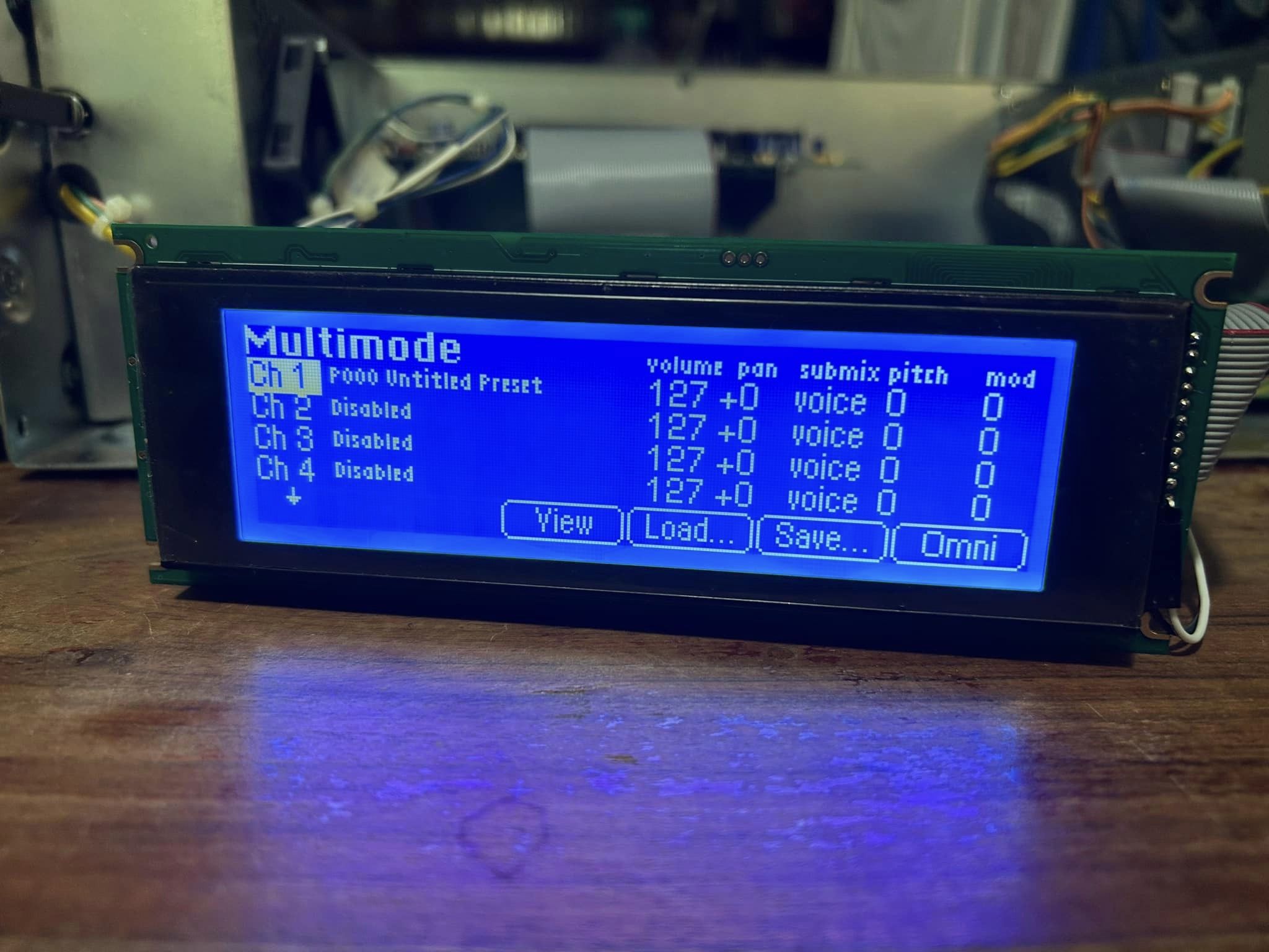
6) I then reconnected the display only and made a quick test. The display worked but was really too bright, it was only barely visible at an 80-90 degree angle.
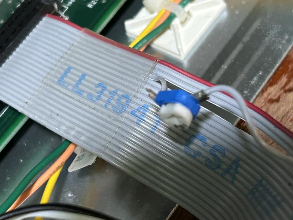
So I decided to add a small trimmer to pin 4, wich controls the voltage for the LCD. I have carefully cut the flat cable on the 4th row, and soldered a 100K trimmer so I was able to coarsely adjust the brightness on the screen, and then I was also able to fine-adjust the contrast via the option in the Software.
(thanks to this guy for the idea!)
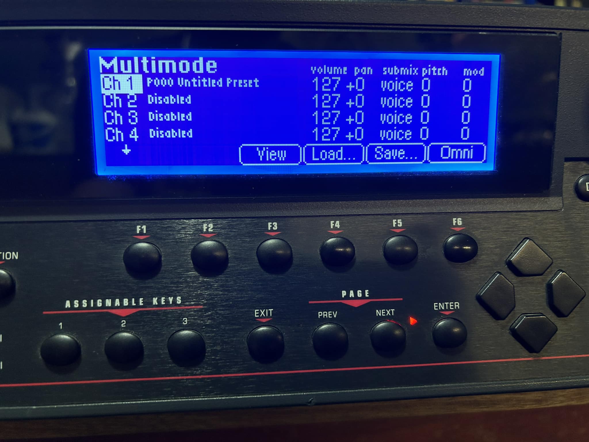
7) a quick test just to confirm that everything was working, and then it was time to start screwing and reconnect everything back (except the inverter, of course).